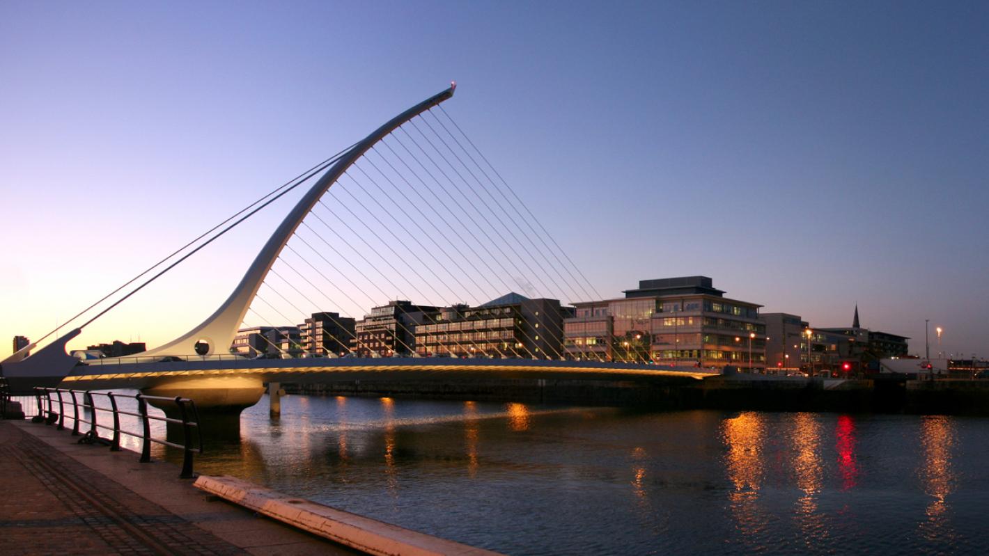
Samuel Beckett Bridge: Winner of the Engineers Ireland Engineering Project of the Year award 2010.
A sleek, asymmetric, signature bridge set in Dublin’s historic docklands

Roughan & O’Donovan assisted lead designer, Santiago Calatrava, with the civil and structural aspects of the bridge design. We also undertook the Category III check, prepared the contract and tender documentation and designed the approach routes to the bridge.
Winner of the Engineers Ireland Engineering Project of the Year award 2010.
The bridge is a cable-stayed, steel box girder structure, with a 120m span across the River Liffey.
90-degree rotation
It rotates through 90-degrees to maintain shipping movements upstream, and has an asymmetric shape, with the base to the cable-stayed steel pylon set outside of the river’s central navigation channel.
Pylon
The pylon curves northwards to a point 46m above the water level with 25 forestay cables set in a ‘harp’ formation.
Traffic
The cross-section of the deck consists of 2 pedestrian and cycle tracks, and 4 lanes for vehicular traffic.
Cable-stays
The cable-stays are all locked coil cables with 25 Nos. 60 mm diameter cables supporting the front span and a total of 6 Nos. 145 mm diameter cables towards the back.
Main support
The main support in the river consists of 1.2m diameter bored cast in-situ piles, with a concrete pilecap supporting a circular concrete pier of varying diameter. This houses the hydraulic turning and lifting equipment and the horizontal and vertical bearings, which support the entire bridge while turning.
Locking pins
At each end of the bridge, locking pins are moved by hydraulic cylinders and locked into the abutments to enable the bridge to carry traffic.
The construction of the river pier and foundation was one of the most significant challenges faced on site and necessitated a 20m2 sheet piled cofferdam.
Design for the open position of the bridge assumed no vehicular loading and no support at the ends. The closed position was subjected to live loads, with support provided at the abutments.
Counterbalance, mass and cable tension were used to minimise the forces, moments and deflections in the pylons and deck. Torsional forces developed in deck were due to a single, central line of cables supporting the main span from a curved pylon.
